BathPi
KO-CHENG CHEN, LIFEI ZHU, LISHAN QIAN, ZIYU DAI
- Video Link: BathPi
- video Password: welove12740
Introduction
- This project is designed to detect the water level and water temperature inside a bathtub. The project consists of two parts; the first part uses water level and temperature sensors to detect bathtub water level and water temperature, the second part uses the buzzer and LED lights to notify the user of the bathtub water level and temperature.
Motivation
- Imagine being back home late with an unfinished assignment and at the same time in need of a bath. You are in a dilemma, as it is approaching assignment due time and need to frequently check the bathtub water situation. (Or you may somehow have an urgent cause to go outside while running bath water)
- Therefore, an intelligent Bathtub monitoring, recording and notification system is proposed to reduce manual checks of bathtub situation to save time. We focus on bathing water temperature and water level conditions and need a creative way to convey the current situation to our users.
Goals
- Water level and temperature sensor collect real-time bathtub’s water level and water temperature data.
- The buzzer buzzes differently to signal different water levels and water temperatures
- Remote access to the real-time sensor’s data via OpenChirp.

Figure 1 Diagram of Project Goal
For Progress Report
Current Progress
- Install and run two Raspberry Pis. (Shown in Figure 1 and 2)
- Setup the water level sensor module
- Setup two DS18B20 temperature module
- Sending data between two raspberry pi by MQTT. (Shown in Figure 3)
- Generate different sounds with buzzer sensor module
- We have learned how to transfer data between two raspberry pi.
- We have processed using a buzzer to generate different sounds.
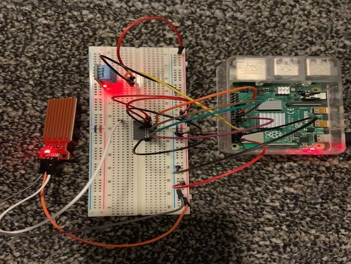
Figure 2 Raspberry Pis of collect sensor’s data and sending data
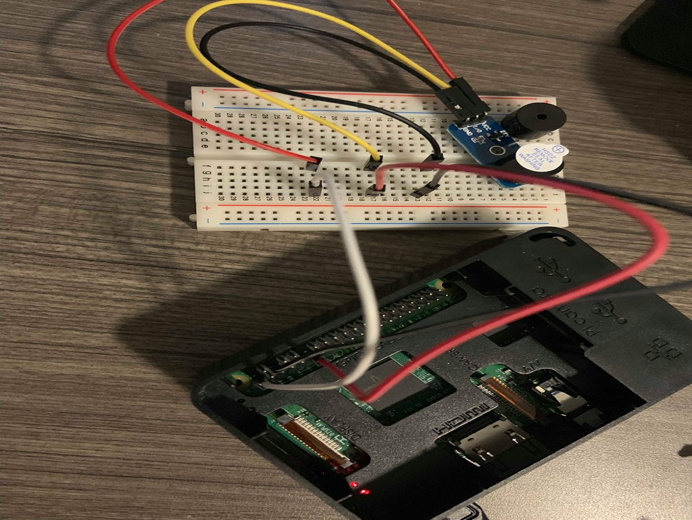
Figure 3 Raspberry Pis of receiving data
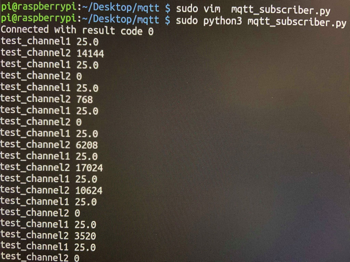
Figure 4 Data sending between two Pis by MQTT service
Problems Encountered
- When using MQTT receiving data, the data is not the same as the original one.
Future Plan
- Get familiar with MQTT package encoding formats
- Organize jumper wires for sleek and more product-like appearance
- Program and debug final code in python
- Conduct a field test
- Make a small model that simulates the field environment for class demonstration
Methodology
Phenomena of Interest
Water Level Detection:
When the water level reaches the warning level, water will flood a part of the sensor, the sensor’s output voltage will change to signify the situation. To monitor desired water level, stick the sensor at the same height level as desired water level.
Temperature Detection:
We need the average water temperature in the bathtub considering the fact that it may not be plausible to consider water temperature distributed across the bathtub based on a single point of measurement. We set up three DS18B20 Temperature Sensors, one inserted in the bread board (the transducer part is utilized, readings are not recorded), two waterproof cable-typed temperature sensors are stuck on the upper and the rear end of the bathtub’s inner surface.
Sensors Used
Water Level sensor
Parameters:
- Working voltage: 5V/3.3V
- Working Current: <20ma
- Width of detection: 40mm×16mm
- Output voltage signal: 0~4.2V

Figure 5 Water level sensor
Paramters:
- Operating voltage: 3V to 5V
- Temperature Range: -55°C to +125°C
- Accuracy: ±0.5°C
- Output Resolution: 9-bit to 12-bit (programmable)
- Unique 64-bit address enables multiplexing
- Conversion time: 750ms at 12-bit
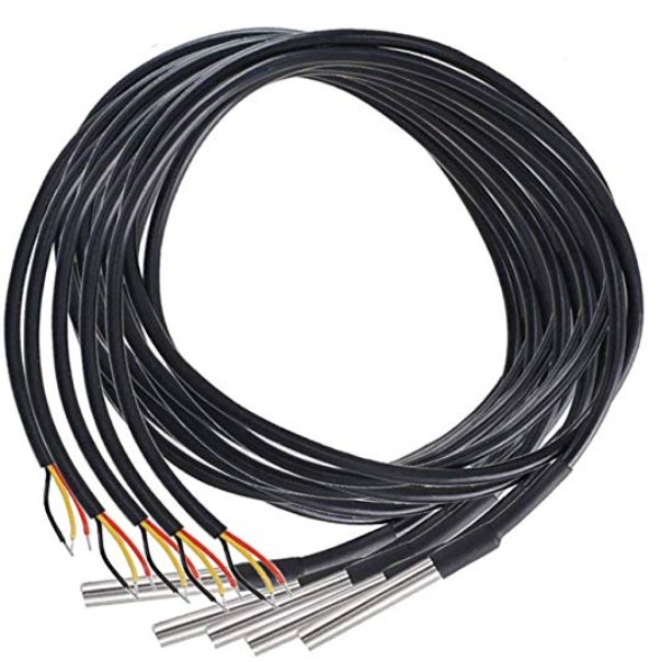
Figure 6 Temperature Sensor: DS18B20
Signal Conditioning and Processing
When the water level sensor detects that the water level reaches or exceeds the alert level, it will automatically trigger the buzzer to play the Bee music for the user to be notified to close the tap and prepare for a bath. As water is added into the bathtub, two temperature sensors will continuously monitor the water temperature. When the water temperature is higher than what users expect, the LED light will glow red; when the water temperature is lower than the lower-bound temperature, the LED light will glow blue; when the water temperature is within the desirable range, LED light will glow green.
Experiments and Results
Step 1: Install OS for two Raspberry pi.
Step 2: Install Useful Packages
Step 3: Setup water level sensors module
- Follow the Figure to setup water level sensors
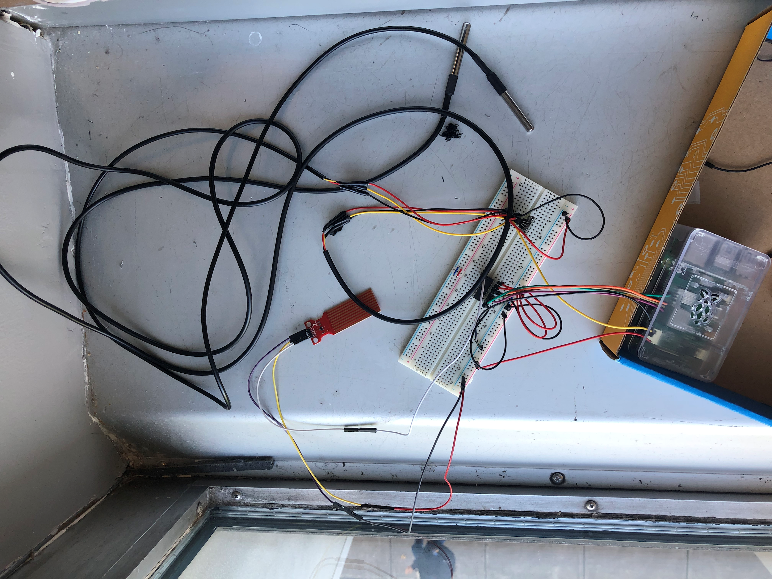
Figure 7 setup a water level sensor
Step 4: Setup waterproof DS18B20 temperature sensor modules
- Follow the Figure Setup the temperature sensor module. (Same figure in setting up water level sensor)
- Notice that we use multiple temperature sensors by connecting them in parallel
Step 5: Setup buzzer module
- Follow the Figure Setup the buzzer module

Figure 8 setup buzzer module
Step 6: Setup LED light module
- Follow the Figure Setup the LED light module(Same figure in setting up buzzer module)
Step 7: Write Python code to configure sensors’ active
- The following is python code
#DS18B20 Setup
os.system('modprobe w1-gpio')
os.system('modprobe w1-therm')
device_folder1 = '/sys/bus/w1/devices/28-031597797e71'
device_file1 = device_folder1 + '/w1_slave'
device_folder2 = '/sys/bus/w1/devices/28-0203917756c6'
device_file2 = device_folder2 + '/w1_slave'

#Setup Water level sensor
spi = busio.SPI(clock=board.SCK, MISO=board.MISO, MOSI=board.MOSI)
cs = digitalio.DigitalInOut(board.D5)
Create an MCP3008 object
mcp = MCP.MCP3008(spi, cs)

#Create an analog input channel on the MCP3008 pin 0
channel = AnalogIn(mcp, MCP.P0)
def read_temp_raw1():
   f = open(device_file1, 'r')
   lines = f.readlines()
   f.close()
   return lines
def read_temp1():
   lines = read_temp_raw1()
   while lines[0].strip()[-3:] != 'YES':
       time.sleep(0.2)
       lines = read_temp_raw1()
   equals_pos = lines[1].find('t=')
   if equals_pos != -1:
       temp_string = lines[1][equals_pos+2:]
       temp_c = float(temp_string) / 1000.0
       return (temp_c)
def read_temp_raw2():
   f = open(device_file2, 'r')
   lines = f.readlines()
   f.close()
   return lines
def read_temp2():
   lines = read_temp_raw2()
   while lines[0].strip()[-3:] != 'YES':
       time.sleep(0.2)
       lines = read_temp_raw2()
   equals_pos = lines[1].find('t=')
   if equals_pos != -1:
       temp_string = lines[1][equals_pos+2:]
       temp_c = float(temp_string) / 1000.0
       return (temp_c)
sensor1 = "temperature"
sensor2 = "water_level"
bathpi.device_state[sensor1] = 0
bathpi.device_state[sensor2] = 0
while True:
   temp1 = read_temp1()
   temp2 = read_temp2()
   temp1 = (((temp1 - 0.375) * 70) / 68.187) + 0.01
   temp2 = (((temp2 - 0.125) * 70) / 72.187  + 0.01
   temp = (temp1+temp2)/2
   print('Temperature: ' + str(temp) + ' C')
   print('ADC Voltage: ' + str(channel.voltage) + 'V')
   bathpi.publish("openchirp/device/"+username+"/"+sensor1, payload=temp, qos=0,
retain=True)
   bathpi.publish("openchirp/device/"+username+"/"+sensor2,
payload=channel.voltage, qos=0, retain=True)
   publish.single(MQTT_PATH1, temp, hostname=MQTT_SERVER)
   publish.single(MQTT_PATH2, channel.voltage, hostname=MQTT_SERVER)
   time.sleep(1)
Step 8: Write a python code to configure buzzer and LED light active
- The following is python code
import RPi.GPIO as GPIO
import time
import paho.mqtt.client as mqtt
import os

MQTT_SERVER = "100.64.1.189"
MQTT_PATH1 = "temperature"
MQTT_PATH2 = "waterlevel"

Buzzer = 11
RED = 16
GREEN = 22
BLUE = 18

CL = [0, 131, 147, 165, 175, 196, 211, 248]
CM = [0, 262, 294, 330, 350, 393, 441, 495]
CH = [0, 525, 589, 661, 700, 786, 882, 990]

high = [CL[1], CL[1], CL[1]]
beat_high = [1, 1, 1]

low = [CH[7], CH[7], CH[7]]
beat_low = [1, 1, 1]

song_bee = [CM[5], CM[3], CM[3], CM[4], CM[2], CM[2], CM[1], CM[2], CM[3],
            CM[4], CM[5], CM[5], CM[5], CM[5], CM[3], CM[3], CM[4], CM[2],
            CM[2], CM[1], CM[3], CM[5], CM[5], CM[3], CM[2], CM[2], CM[2],
            CM[2], CM[2], CM[3]]
beat_bee = [0.5, 0.5, 0.5, 0.5, 0.5, 0.5, 0.5, 0.5, 0.5, 0.5, 0.5, 0.5, 0.5,
            0.5, 0.5, 0.5,0.5, 0.5, 0.5, 0.5, 0.5, 0.5, 0.5, 0.5, 0.5, 0.5,
            0.5, 0.5, 0.5, 0.5]

def setup():
    GPIO.setmode(GPIO.BOARD)
    GPIO.setup(Buzzer, GPIO.OUT)
    GPIO.setup(RED, GPIO.OUT)
    GPIO.output(RED, 0)
    GPIO.setup(GREEN, GPIO.OUT)
    GPIO.output(GREEN, 0)
    GPIO.setup(BLUE, GPIO.OUT)
    GPIO.output(BLUE, 0)
    global Buzz
    Buzz = GPIO.PWM(Buzzer, 440)

def bee():
    Buzz.start(50)
    GPIO.output(BLUE, 1)
    print ('\n\n Time to have a bath...')
    for i in range(1, len(song_bee)):
        Buzz.ChangeFrequency(song_bee[i])
        time.sleep(beat_bee[i] * 0.5)
    Buzz.stop()
    GPIO.output(BLUE, 0)

def temphigh():
    print ('\n\n Temperature too high...')
    Buzz.start(50)
    GPIO.output(RED, 1)
    for i in range(1, len(high)):
        Buzz.ChangeFrequency(high[i])
        time.sleep(beat_high[i] * 0.5)
    GPIO.output(RED, 0)
    Buzz.stop()

def templow():
    print ('\n\n Temperature too low...')
    Buzz.start(50)
    GPIO.output(GREEN, 1)
    for i in range(1, len(low)):
        Buzz.ChangeFrequency(low[i])
        time.sleep(beat_low[i] * 0.5)
    GPIO.output(GREEN, 0)
    Buzz.stop()
Step 9: : Creating an IoT Device
- install client with
import paho.mqtt.client as mqtt - Create a MQTT client for device, following the template code(see reference[7] below). Modify all parameters to our device.
- Set up MQTT Path, setting the hostname (of which we used the IP address of the broker) and channels to identify communication.
#Setup MQTT Path
MQTT_SERVER = "100.64.1.189"
MQTT_PATH1 = "temperature"
MQTT_PATH2 = "waterlevel"
With data readings:
For publisher:
- publish on Openchirp
bathpi.publish("openchirp/device/"+username+"/"+sensor1, payload=temp, qos=0,retain=True) bathpi.publish("openchirp/device/"+username+"/"+sensor2, payload=channel.voltage, qos=0, retain=True) - Publish to broker
publish.single(MQTT_PATH1, temp, hostname=MQTT_SERVER)
publish.single(MQTT_PATH2, channel.voltage, hostname=MQTT_SERVER)
With (Topic, payload(which is defined when taking the reading), hostname)
For Subscriber(receiver RPi):
- set path
MQTT_SERVER = "100.64.1.189" MQTT_PATH1 = "temperature" MQTT_PATH2 = "waterlevel" - subscribe on desired channels
def on_connect(client, userdata, flags, rc): print("Connected with result code "+str(rc)) client.subscribe(MQTT_PATH1) client.subscribe(MQTT_PATH2) - decoding and responding to values through buzzers and LEDs
def on_message(client, userdata, msg): check = msg.payload.decode() channel_and_value = dict() topic_name = msg.topic.split("/")[-1] if topic_name == 'test_channel1': channel_and_value[topic_name] = msg.payload.decode() temp = msg.payload.decode() temp = float(temp) print('temp: '+ str(temp)) if temp > 25: temphigh() elif temp < 15: templow() elif topic_name == 'test_channel2': channel_and_value[topic_name] = msg.payload.decode() water_level = msg.payload.decode() water_level = float(water_level) print('water_level: ' + str(water_level)) if water_level >= 1.18: - set connection
if __name__ == '__main__':
  setup()
  client = mqtt.Client()
  client.on_connect = on_connect
  client.on_message = on_message
  client.connect(MQTT_SERVER, 1883, 60)
  client.loop_forever ()

Figure 9 Test Openchirp on the computer

Figure 10 Using phone to check the Openchirp
Experiment
The BathPi have two working parts, which is shown in the device schematic and entity diagram in Figure 9.
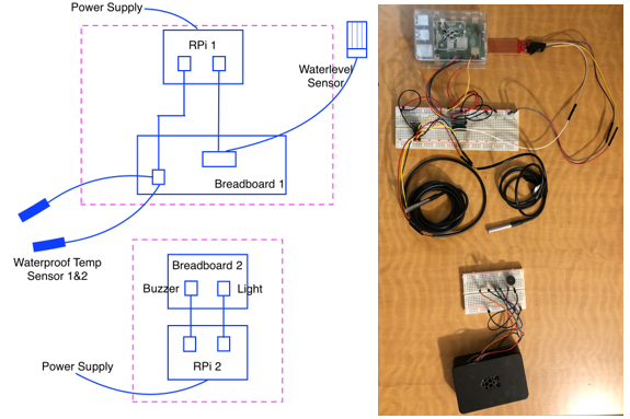
Figure 11 Device schematic and entity diagram
To test the accuracy and fine-tune our temperatures sensors. We calibrated our sensors against thermometers. As the sensor’s data should vary linearly through range, we are using the two-point calibration method, which should give us a linear function to calibrate against, which will help with both slope and offset errors. First point we picked is room temperature water, which is generally the lower bound for bathing water. We took the reading from both the sensor(sensor1) and thermometer(thermo1) Then we switched room temperature water for hot water and took the reading from the sensor(sensor2) and thermometer(thermo2) Rangesensor=sensor2-sensor1 Rangethermo=thermo2-thermo1 temp is the temperature data collected when running our system. We can yield the corrected value as a function of temp (which can be written within our code ): CorrectedValue = (((temp – sensor1) * Rangethermo) / Rangesensor) + thermo1
Do this for both temperature sensors separately to get individual corrected values. Then take the average of them or proceed with any other operations.
Discussion
Project Rewards
We started off the course with next to nothing knowledge on sensors, but with the help of course lectures, course tutorials and google, we managed to delve into the parameters and principles and create a presentable circuit system to our hearts’ desires. We learnt about resolution of sensors and ADCs. We learned new means of transmitting data-MQTT protocol and how it can be implemented in Python code to not only transmit information between two RPi with the help of a broker. We also learned to publish information on Openchirp for good visualization of current and historical data and of course, enable access on any mobile device.
We think the highlight of our project is the use of MQTT protocol, which we used to set up data transmission between two Raspberry Pi and send information to be displayed on Openchirp.
Results and Possible Future Optimization
This project has several parts that needs further improvements.
First, the water level sensor we used is not very accurate. For extreme situations such as relatively high temperatures, the sensor becomes inaccurate by default as it’s out of range. In our field test, we also found out that the sensor’s accuracy is affected by the pressure on the sensor, which may need more calibration. In addition, it may be better to set up more water level sensors along bathtub height so that we are notified of water level situation at a distribution of different water levels.
Second, considering that water temperature will not distribute evenly in an ideal fashion in the bathtub, it will be more accurate to assume final water temperature to be more complex than just an average of temperatures at two discrete testing points. Thus a more accurate system will need to incorporate mathematical temperature modeling.
Acknowledgements
Professor Mario and the TAs gave us clear guide which are crucial for the completion of our project. Therefore, we want to say “THANKS!”
Also a huge round of applause for our group members for drawing up the time and effort to complete this project among heavy CEE MS workload. Taking the time to work together and discuss really helped to clear out the cloudy part in our individual’s knowledge field and we stand stronger as a team.
Reference
[1] http://www.circuitbasics.com/raspberry-pi-ds18b20-temperature-sensor-tutorial/
[2] https://tutorials-raspberrypi.com/raspberry-pi-mqtt-broker-client-wireless-communication
[3] http://www.d3noob.org/2015/02/raspberry-pi-multiple-temperature.html
[4] https://www.sunfounder.com/learn/sensor-kit-v2-0-for-raspberry-pi-b-plus/lesson-10-buzzer-module-sensor-kit-v2-0-for-b-plus.html
[5] https://tutorials-raspberrypi.com/raspberry-pi-mqtt-broker-client-wireless-communication/
[6] https://inferlab.github.io/12740/tutorials/openchirp.html
[7] https://inferlab.github.io/12740/tutorials/adc.html
[8] https://learn.adafruit.com/calibrating-sensors/two-point-calibration